The Groma was the simple surveying tool used in Babylonia, Ancient Greece, Ancient Rome and Medieval Europe. It was constructed with a staff placed in the ground supporting a horizontal cross with 5 plumb lines handing from it. Understanding how a Groma works and can be self-compensated for accurate angle measurement is a great way to start gaining a full understanding of the principles of angle measurement and surveying. The Groma self-compensation and surveying experiments on this page, followed by a similar exercises relating to a theodolite, will serve as a great introduction to the principles of angle measurement and surveying.
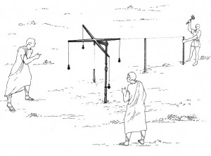
This simple experiment will substitute drawing pins pointing up for the plumb lines which were used as sighting lines and cardboard instead of a wooden frame. You will need the following:-
- 9 Drawing Pins
- A sheet of modelling card
- Some sticky-back tape
- Some blue tack
- Scissors
- A pen
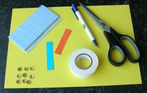
First you will need to cut two small strips of card, each about 15 mm by 80 mm. I have used different colours to make them clearer to see but you could just cut them from the main sheet of card. You must then push a drawing pin through the end of each piece of card and one fixed in the main sheet of card, about 100 mm from one corner. If you are a child then ask an adult to help you do this.
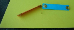
Next push the strips of card into the fixed drawing pin in the main sheet of card to form a cross which can rotate about the central pin fixed in the sheet of card. Use a small piece of sticky-back tape to temporarily fix the angle between the two arms of the cross and also place another drawing pin poking up somewhere towards the other end of the large sheet of card. The drawing pins poking up from the arms of our ‘groma’ are equivalent to the plumb lines which are used for slighting along and the drawing pin poking up some distance away is a fixed point of reference which might be a tree or a building.

Now we can make our first sighting to align the ‘groma’ with our point of reference. Look down the length of the card past the ‘groma’ and towards the reference point and rotate the ‘groma’ until the sighting line pins at the ends both line up with the reference point.
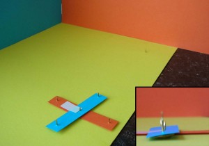
Next we would sight along the other pins arranged at a right angle to the first and an assistant would place a sighting rod in the ground. We will use drawing pins with blue-tack on the bottom in place of sighting rods!
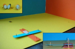
Now we rotate the ‘groma’ through 90 degrees and repeat the procedure. The arm which was pointing at the ‘sighting rod’ is used to align the ‘groma’ with the fixed reference and the arm which was aligned with the fixed reference is used to place the ‘sighting rod’. If the ‘groma’ is not correctly adjusted this time the ‘sighting rod’ will be placed in a different position.
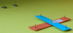
We place a third ‘sighting rod’ mid-way between the first two. The tape should be lifted to allow the arms of the cross to rotate relative to each other. It is now possible to correct the angle of the arms by aligning one with the fixed reference and the other with the mid-way ‘sighting rod’. The whole process can be repeated in order to increase the accuracy of your ‘groma’.
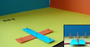
You have now performed a self-compensation of your ‘groma’ and are ready to place sighting rods along straight lines at right angles to each other to lay out the perfect Roman roads and city structures!
An interesting project. Thank you.
Could you tell me where the sketch of surveyors using a Groma comes from. Is it copyright ?
Roger Fisher
Land Surveyor
Very nice blog post. I absolutely love this site. Thanks!